JasonE
New Member
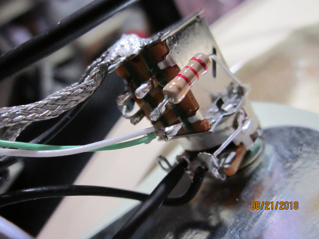
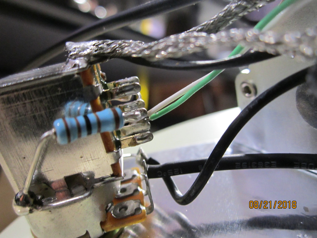
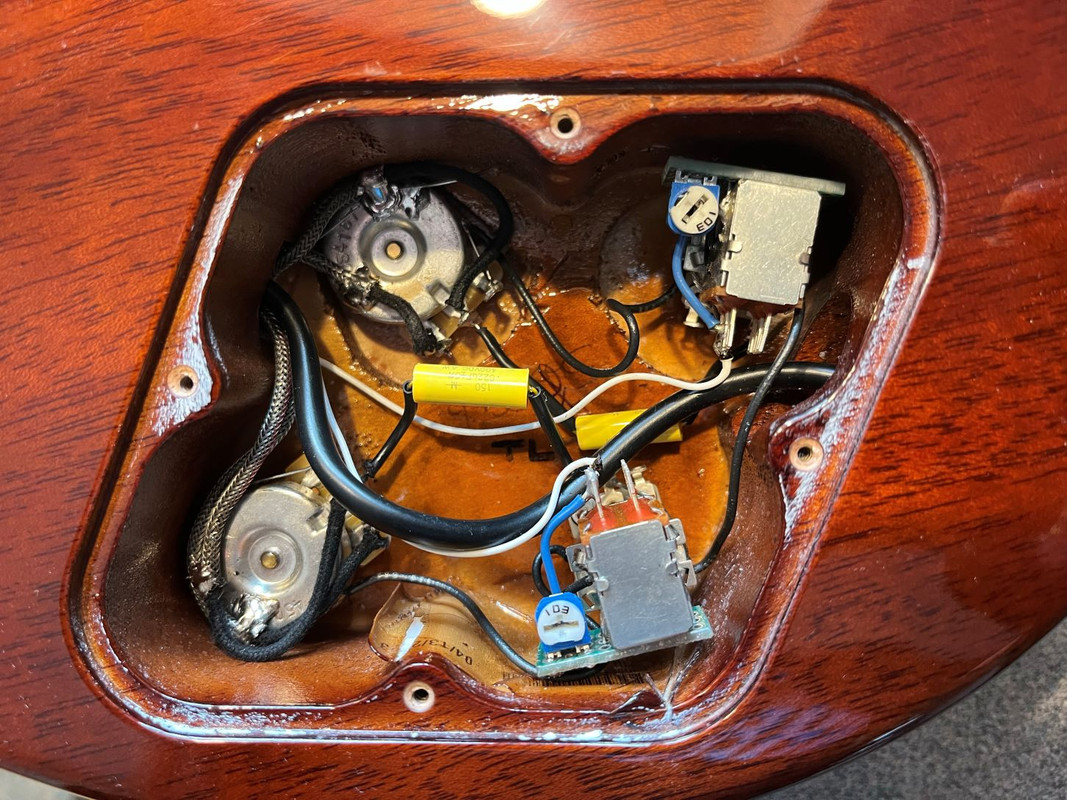
His way will work. I actually pulled the tone control out of one I added them to so I could get to it easier. I left the wires soldered to it but was able to get all around it easier. I soldered the resistors to the sides of the switch casing like PRS does instead of to the bottom of the casing like he did. There are a number of models that have these resistors in them so you can probably find a wiring diagram that is very close to your guitar if you want to see what that looks like.Is this video the correct installation.